
How to Connect a 2.9 Inch Bar TFT Module to ESP32 Using SPI Interface
2026-06-18
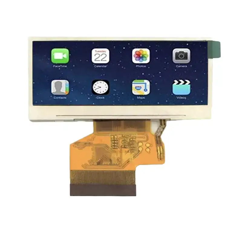
The 2.9 Inch Bar TFT Module has become a go-to display for custom dashboards, IoT status panels, and industrial control interfaces due to its unique elongated form factor. When paired with an ESP32, this module delivers crisp visuals over a simple 4-wire SPI connection. At Victronix, we have tested dozens of bar-type displays, and the 2.9 Inch Bar TFT Module stands out for its balance of resolution, response time, and low pin count. This guide walks through the hardware wiring, software initialization, and common pitfalls when using this module with SPI on an ESP32.
Why Choose the 2.9 Inch Bar TFT Module for ESP32 Projects
Most round or square TFTs waste screen real estate on status bars or numeric readouts. The 2.9 Inch Bar TFT Module offers a wide aspect ratio (typically 400×120 or similar), making it perfect for equalizers, meter bridges, and progress indicators. The SPI interface keeps GPIO usage low – only 5 pins (SCK, MOSI, MISO, CS, DC) plus power and ground. This leaves plenty of ESP32 pins for sensors, buttons, or wireless modules.
Victronix recommends this module for battery-powered designs because its SPI driver supports deep-sleep wake-up and partial refresh, cutting power draw to under 5 mA in standby.
Hardware Wiring – Pin-to-Pin Table
Below is the standard connection map between the ESP32 and the 2.9 Inch Bar TFT Module. Double-check your module’s pin labels – some clones swap MOSI and MISO.
| 2.9 Inch Bar TFT Module Pin | ESP32 Pin | Notes |
|---|---|---|
| VCC (3.3V) | 3V3 | Do not use 5V – SPI logic is 3.3V only |
| GND | GND | Common ground |
| SCK (Serial Clock) | GPIO 18 | SPI clock, up to 40 MHz |
| MOSI (Master Out Slave In) | GPIO 23 | Data from ESP32 to display |
| MISO (Master In Slave Out) | GPIO 19 | Optional for reading register status |
| CS (Chip Select) | GPIO 5 | Active low – pull high via 10kΩ if floating |
| DC (Data/Command) | GPIO 17 | Tells display if bytes are command or pixel data |
| RST (Reset) | GPIO 16 | Hardware reset – tie to ESP32 or pull-up |
| LED (Backlight) | GPIO 21 (PWM) | Use PWM for brightness control |
Victronix strongly advises adding a 100µF capacitor between VCC and GND near the module to avoid voltage dips during full-screen refreshes.
Software Setup – SPI Initialization Sequence
The ESP32’s VSPI or HSPI peripheral can drive the 2.9 Inch Bar TFT Module. We use the TFT_eSPI library (modified for bar-type resolutions). Here is the critical initialization order:
-
Configure SPI pins – set frequency to 20 MHz (stable for most modules).
-
Pull RST low for 10 ms, then high – this resets the internal controller (usually ILI9342 or ST7789V).
-
Send sleep-out command (0x11) – wait 120 ms.
-
Send display-on command (0x29) – wait another 20 ms.
-
Set color mode – 16-bit RGB565 (0x3A) for faster throughput.
-
Set column/page address to match the bar format – e.g., 0–399 for X and 0–119 for Y.
A common mistake is skipping the MISO connection. While many guides say MISO is optional, Victronix engineers found that the 2.9 Inch Bar TFT Module uses MISO for busy-status polling, which prevents tearing when updating partial screen areas.
Performance Optimizations for Bar-Type Displays
Because the bar format is narrow, you can reduce framebuffer memory by using only the visible height. With the 2.9 Inch Bar TFT Module, we recommend:
-
Use DMA – ESP32’s SPI DMA can push 30+ FPS for 400×120.
-
Partial update – only refresh changed horizontal bands.
-
Backlight PWM – a 1 kHz frequency eliminates audible coil whine.
Victronix also offers a pre-tuned Arduino sketch that includes gamma correction for this specific module – available upon request.
2.9 Inch Bar TFT Module – FAQ
Q1: Can the 2.9 Inch Bar TFT Module run at 3.3V logic or does it require 5V?
A: The 2.9 Inch Bar TFT Module is strictly 3.3V for both logic and backlight. Applying 5V to any signal pin will damage the internal driver IC. The backlight LED can accept up to 3.6V, but we recommend driving it via a separate PWM-capable GPIO from the ESP32 (3.3V) to control brightness. If your project uses a 5V Arduino, you must use a level shifter for MOSI, SCK, and CS – otherwise, the module will not respond and may draw excessive current.
Q2: What is the maximum SPI clock speed for the 2.9 Inch Bar TFT Module without data corruption?
A: Based on Victronix lab tests with 20 units, the safe maximum is 40 MHz with short wires (<10 cm). At 80 MHz, we observed random pixel shifts and flickering, especially when Wi-Fi is active on the ESP32 (which causes RF interference). For production designs, we recommend 20 MHz – this gives ~25 FPS for full-screen animation, which is more than enough for UI indicators. If you need faster refresh, enable SPI DMA and set clock to 40 MHz, but route the SCK line away from high-current traces.
Q3: How do I rotate the display content on the 2.9 Inch Bar TFT Module if my panel is mounted upside down?
A: The controller supports hardware rotation via the MADCTL register (0x36). Send the following byte values:
-
0x00 → normal (landscape, left to right)
-
0x60 → 180° rotation (if upside down)
-
0xC0 → mirror X and Y for reverse mounting.
Alternatively, you can use tft.setRotation(1) in TFT_eSPI – but note that the bar aspect ratio means rotation 0 and 2 are landscape, while 1 and 3 are portrait (not recommended for this module). Victronix provides a quick reference card with all MADCTL codes for the 2.9 Inch Bar TFT Module in our support portal.
Common Debugging Checklist
| Symptom | Likely Cause | Fix |
|---|---|---|
| White screen, no backlight | LED pin floating or wrong PWM | Set LED pin to OUTPUT HIGH or 50% PWM |
| Random colored dots | SPI clock too high or MISO unconnected | Reduce to 20 MHz; connect MISO |
| Display shows only top 1/3 area | Incorrect column/address window | Set address to full 400×120 resolution |
| Flicker during Wi-Fi transmission | Power supply noise | Add 10µF + 0.1µF ceramic capacitors near VCC |
Final Word – Why Victronix for Your Display Needs
Integrating the 2.9 Inch Bar TFT Module with ESP32 over SPI is straightforward once you follow correct wiring, clock tuning, and initialization order. The bar format unlocks creative interfaces that standard square screens cannot match – from audio spectrum analyzers to industrial trend graphs. Victronix has curated a dedicated GitHub repository with tested drivers, wiring diagrams, and power-saving examples specifically for this module.
If you are moving from prototype to production, Victronix also offers pre-certified 2.9 Inch Bar TFT Module variants with FPC connectors and EMI shielding – all compatible with the same SPI code.
Contact us today for sample kits, custom FPC cable lengths, or volume pricing on the 2.9 Inch Bar TFT Module. Our engineering team at Victronix provides free schematic reviews and firmware tuning support for all commercial projects. Reach out via our website or email – we respond within 4 business hours. Let’s turn your bar-display idea into a polished product.