

How to Connect a 4.3" Transmissive IPS Color TFT LCD Display Module via SPI or RGB Interface
2026-06-24
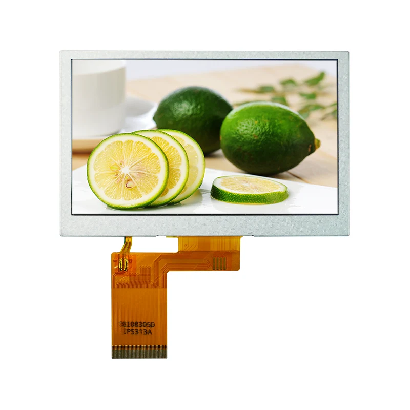
Selecting the proper connection method for a 4.3" Transmissive IPS Color TFT LCD Display Module determines the success of any embedded display project. Tianfu manufactures some of the most reliable modules in this category, offering both SPI and RGB variants to suit different performance requirements. This guide walks through the hardware wiring, software setup, and critical decision factors for each interface, drawing from real-world engineering practices.
Interface Architecture Overview
The fundamental distinction between SPI and RGB lies in where the frame buffer resides. With SPI, the 4.3" Transmissive IPS Color TFT LCD Display Module contains an internal graphics RAM (GRAM) inside the driver controller. The host microcontroller sends high-level commands—draw a rectangle, write text, or update a small region—and the display handles the pixel rendering independently. This offloads memory and processing from the MCU.
RGB mode, in contrast, treats the 4.3" Transmissive IPS Color TFT LCD Display Module as a "dumb" pixel array. Every single pixel must be refreshed continuously by the host, requiring a dedicated LCD controller or a microcontroller with a parallel RGB peripheral. The benefit is raw speed: full-screen video at 60 fps becomes feasible.
Tianfu documents both configurations thoroughly in their product datasheets, including timing diagrams and initialization sequences that are critical for stable operation.
Pin-by-Pin Connection Tables
SPI Interface – 6-Wire Standard Connection
| Tianfu Module Pin | Signal Name | MCU Connection (Example: STM32) | Notes |
|---|---|---|---|
| 1 | VCC (3.3V) | 3.3V rail | Do not exceed 3.6V |
| 2 | GND | GND | Common ground |
| 3 | SCK | SPI_SCK (PA5) | Max 20 MHz for reliable operation |
| 4 | MOSI | SPI_MOSI (PA7) | Master Out Slave In |
| 5 | MISO | SPI_MISO (PA6) | Optional – used for register readback |
| 6 | CS | GPIO (PB12) | Active-low chip select |
| 7 | DC | GPIO (PB13) | Data (high) / Command (low) |
| 8 | RST | GPIO (PB14) | Hardware reset, active-low |
| 9 | BL | PWM-capable GPIO (PB15) | Backlight dimming via duty cycle |
Critical verification: Some Tianfu models integrate a built-in voltage regulator, allowing VCC up to 5V. However, the logic pins remain 3.3V tolerant only. Always consult the specific datasheet for your module revision.
RGB Interface – 24-Bit Parallel Connection
| Signal Group | Tianfu Pin Labels | Count | Description |
|---|---|---|---|
| Red Data | R0 – R7 | 8 bits | Red channel, LSB to MSB |
| Green Data | G0 – G7 | 8 bits | Green channel |
| Blue Data | B0 – B7 | 8 bits | Blue channel |
| Synchronization | HSYNC, VSYNC | 2 | Horizontal and vertical sync pulses |
| Clock | PCLK | 1 | Pixel clock – typical range 5–12 MHz for 480x272 |
| Data Enable | DE | 1 | Active high – indicates valid pixel data |
| Backlight | BL_EN, PWM_DIM | 2 | Enable and brightness control |
| Power | VCC (3.3V), GND | 2 | Main supply and ground |
RGB mode consumes significantly more I/O pins, but Tianfu offers modules with a 40-pin FPC that consolidates all signals into a single flat cable, simplifying PCB layout when using a matching connector.
Software Initialization Sequences
SPI Mode – Recommended Initialization Flow
-
Reset the 4.3" Transmissive IPS Color TFT LCD Display Module by pulling RST low for 10 ms, then high.
-
Send the Sleep Out command (0x11) with a 120 ms delay.
-
Configure the pixel format via command 0x3A – set to 0x55 for 16-bit RGB565 or 0x66 for 18-bit.
-
Set the display on with command 0x29.
-
Optionally adjust gamma, contrast, and inversion settings using vendor-specific registers provided by Tianfu.
For Arduino environments, the TFT_eSPI library supports most Tianfu SPI modules with a simple user setup file. For ESP-IDF or Zephyr, the driver typically uses the ili9488 or st7796 device tree bindings.
RGB Mode – Timing Configuration
RGB mode does not use command sequences over SPI. Instead, the host must generate precise pixel clock and sync signals. For a typical Tianfu 480×272 RGB panel, the timing parameters are:
| Parameter | Value | Tolerance |
|---|---|---|
| Pixel clock frequency | 9.0 MHz | ±5% |
| Horizontal active | 480 pixels | Fixed |
| Hsync front porch | 2 pixels | ±1 |
| Hsync pulse width | 41 pixels | ±2 |
| Hsync back porch | 2 pixels | ±1 |
| Vertical active | 272 lines | Fixed |
| Vsync front porch | 2 lines | ±1 |
| Vsync pulse width | 10 lines | ±2 |
| Vsync back porch | 2 lines | ±1 |
On Raspberry Pi, these values translate directly into the dtoverlay=dpi24 and hdmi_timings parameter string. Tianfu provides pre-calculated overlay files for popular SBCs, reducing setup time considerably.
Interface Selection Matrix
| Application Scenario | SPI Suitability | RGB Suitability | Recommended Tianfu Model |
|---|---|---|---|
| Battery-powered handheld device | Excellent – low power draw | Poor – high current consumption | TF-43SPI-ILI9488 |
| Industrial control panel with touch | Excellent – easy integration with touch controller | Moderate – requires separate touch ADC | TF-43SPI-ST7796 |
| Automotive gauge cluster | Poor – limited refresh for needle animations | Excellent – smooth 60 fps updates | TF-43RGB-RK043 |
| Portable gaming console | Moderate – scrolling may tear | Excellent – full motion video support | TF-43RGB-HX8257 |
| Medical monitoring device | Excellent – static graphs and text | Overkill – unnecessary complexity | TF-43SPI-ILI9488 |
| Home automation touchscreen | Excellent – menu-based UI | Acceptable but not required | TF-43SPI-ST7796 |
Tianfu clearly labels each module's interface type on both the packaging and the FPC tail, preventing ordering errors.
Common Pitfalls and Debugging
SPI connectivity issues often stem from incorrect DC pin toggling. The 4.3" Transmissive IPS Color TFT LCD Display Module expects the DC line to change state before each 8-bit transfer. If the host toggles DC after the clock starts, the controller misinterprets data as a command. Using a logic analyzer to verify DC versus SCK alignment resolves this quickly.
RGB failures are usually related to clock jitter or voltage level mismatches. The parallel data lines must settle before each PCLK rising edge. For long FPC cables, Tianfu recommends adding series resistors (22–33 Ω) on each data line to dampen reflections. Without these, ghost pixels and horizontal streaks appear.
4.3" Transmissive IPS Color TFT LCD Display Module – FAQ
Q1: Can I switch a Tianfu module from SPI to RGB by reconfiguring software alone?
A1: No, this is impossible. The driver IC is physically different between SPI and RGB variants. SPI models (e.g., ILI9488, ST7796) contain internal GRAM and a command interpreter that processes serial data. RGB models (e.g., RK043FN, HX8257) lack this interpreter and require parallel pixel data on every clock cycle. Even if you connect all RGB pins to an SPI-capable MCU, the internal silicon will not respond to SPI protocol frames. Tianfu produces separate product lines – check the model suffix: "-SPI" or "-RGB" before purchasing. The FPC connector pinout also differs, so a hardware swap is not a simple re-solder job.
Q2: What is the practical refresh rate limit for SPI mode on a 4.3" Transmissive IPS Color TFT LCD Display Module?
A2: With a 20 MHz SPI clock and 16-bit RGB565 color, each pixel transfer consumes 16 clock cycles. To fill 480×272 pixels (130,560 pixels), the raw data payload is approximately 2.09 million bits. Adding command overhead and CS toggling, a full-screen update takes about 120–150 ms. This yields 7–8 fps for full redraws. However, partial updates – changing only a 100×100 region – can achieve 30 fps or higher. Tianfu recommends using the display's built-in window address command (0x2A and 0x2B) to restrict writes to modified areas, dramatically boosting perceived performance for GUI applications. For true video playback, RGB is the only viable route.
Q3: How do I determine the correct pixel clock for my Tianfu RGB module when using a non-standard resolution?
A3: The pixel clock must satisfy this equation: PCLK = (H_active + H_blank) × (V_active + V_blank) × Refresh_Rate. For a 480×272 panel with standard blanking (H_blank = 45 pixels, V_blank = 14 lines) and a target of 60 Hz: (480 + 45) × (272 + 14) × 60 = 525 × 286 × 60 = 9,009,000 Hz (≈ 9 MHz). Tianfu datasheets include the minimum and maximum PCLK ranges – do not exceed these values. If the clock is too low, the image flickers; if too high, the internal timing generator fails and displays a black screen. Use an oscilloscope to measure PCLK frequency during development. Most Tianfu RGB modules tolerate a ±10% variation, but stable operation favors the exact recommended value from the timing table.
Practical Implementation Checklist
-
Verify the Tianfu module interface type (SPI or RGB) from the product label.
-
Measure your MCU's logic level – 3.3V is safe; 5V requires a level shifter.
-
For SPI, assign CS and DC to any GPIO, but use hardware SPI pins for SCK and MOSI.
-
For RGB, allocate 24 GPIOs for data plus 4 for sync and clock – consider a parallel bus peripheral.
-
Configure backlight PWM with a frequency above 1 kHz to avoid audible coil whine.
-
Test with a basic "fill screen red" command before advancing to complex graphics.
-
Integrate the touch controller separately – Tianfu modules often include a capacitive touch FPC but it operates over I2C, independent of the display interface.
Contact Us
Choosing between SPI and RGB for a 4.3" Transmissive IPS Color TFT LCD Display Module involves trade-offs that depend on your specific MCU capabilities, power budget, and frame rate targets. Tianfu supports engineers through every stage – from sample evaluation to mass production. Our technical team provides custom timing files, ported driver libraries for STM32, ESP32, and i.MX RT platforms, and FPC cable assemblies tailored to your PCB footprint. For direct assistance, visit the Tianfu contact page to submit your project requirements. We respond to every inquiry within one business day and offer complimentary design reviews for volume orders. Let Tianfu help you turn your display concept into a reliably manufactured product.