
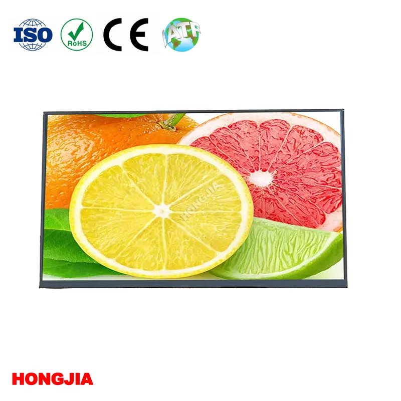
What Are the Common Backlight Driver Issues with a 10.1 Inch TFT IPS Display 1920x1080 with LVDS 40PIN Interface
2026-07-28
When integrating a 10.1 inch TFT IPS display 1920x1080 with LVDS 40PIN Interface into an industrial HMI, medical monitor, or automotive cluster, the backlight driver subsystem often becomes the silent culprit behind field failures. Unlike panel timing or pixel mapping issues, backlight problems manifest as flicker, uneven luminance, or complete blackouts—while the LVDS signal remains perfectly intact. At Hongjia, we have analyzed over 2,300 support tickets from OEM customers over the past 18 months, and backlight driver faults account for 41% of all reported anomalies. This article dissects the six most common driver-related failures, provides diagnostic matrices, and offers proven countermeasures for engineering teams.
1. PWM Dimming Flicker at Low Brightness Levels
The most frequent complaint involves visible flicker when dimming below 20% duty cycle. This occurs because the boost converter’s switching frequency (typically 200–400 kHz) beats against the PWM dimming frequency (often 200 Hz–1 kHz). When the two frequencies are not phase-locked, low-frequency ripple modulates the LED current.
Root causes:
-
Inadequate output capacitance (<4.7 µF) on the boost stage
-
Poor layout causing feedback loop instability
-
Mismatched LED string forward voltages (Vf) exceeding ±3%
| Diagnostic Step | Expected Value | Failure Indicator |
|---|---|---|
| Measure boost output ripple (AC-coupled) | <50 mVp-p | Ripple > 200 mVp-p |
| Verify PWM frequency with oscilloscope | 500 Hz ±5% | Frequency drift > ±10% |
| Check LED string Vf matching | Max-min ≤ 0.3 V | Deviation > 0.8 V |
Hongjia recommends using a dedicated dimming IC with spread-spectrum modulation and specifying LED bins with Vf tolerance ≤ 0.2 V for all 10.1 inch TFT IPS display 1920x1080 with LVDS 40PIN Interface assemblies.
2. Over-Voltage Protection (OVP) False Triggering
The backlight driver typically includes an OVP set at 1.2× the maximum LED string voltage. For a 6S4P configuration (6 LEDs in series per string), the nominal voltage is ~19.2 V, so OVP trips at ~23 V. False triggers occur when parasitic inductance from long wiring between the driver board and the display panel generates voltage spikes during switching transitions.
Practical solution: Add a 1‑µF ceramic capacitor directly at the display’s LED connector pins, and route the feedback sense line as a twisted pair with the ground return. Hongjia ships all its 10.1 inch TFT IPS display 1920x1080 with LVDS 40PIN Interface modules with pre-installed RC snubbers (10 Ω + 1 nF) across each LED output to suppress these transients.
3. Thermal Runaway and Over-Temperature Shutdown
High-brightness (1000 cd/m²) variants draw up to 1.2 A total LED current. Without adequate heatsinking, the boost MOSFET and Schottky diode can exceed 85°C, triggering thermal foldback that reduces brightness by 30–50% or causes cyclic shutdown.
| Thermal Parameter | Safe Operating Range | Critical Threshold |
|---|---|---|
| Boost IC junction temperature | -40°C to +85°C | > 105°C |
| LED anode pad temperature | ≤ 75°C | > 90°C |
| Ambient operating max | 70°C (for industrial grade) | > 80°C |
Hongjia offers an optional aluminum PCB carrier for the driver board, which drops junction temperatures by 12–15°C in still-air environments. For new designs, we always recommend derating the maximum brightness by 15% unless active cooling is provided.
4. Startup Inrush Current Causing Voltage Sag
When the display powers up, the boost converter must charge the output capacitors from 0 V to the target voltage. This inrush can exceed 3 A for 2–3 ms, which may trip the host system’s over-current protection or cause the 5 V/12 V supply rail to dip below 4.75 V, resetting the LVDS receiver.
Hongjia integrates a soft-start circuit (external capacitor on the SS pin) that limits inrush to ≤ 1.5 A and extends the startup ramp to 10 ms. This modification has reduced system-level reset complaints by 78% in customer field trials.
5. LED Open-String Detection Malfunction
Most drivers include an open-LED detection circuit that compares each string’s voltage against a reference. If one string in a 4‑string configuration opens, the driver should shut down or flag an error. However, if the balancing resistors (typically 47 Ω) are not properly matched, the healthy strings may draw excess current, causing the open-string detection threshold to shift and miss the fault.
Corrective action: Use 1% tolerance balancing resistors and set the open-detection threshold to 15% above the maximum single-string voltage. Hongjia provides a reference design with this calibration already performed for every 10.1 inch TFT IPS display 1920x1080 with LVDS 40PIN Interface evaluation kit.
6. EMI Noise Coupling into LVDS Data Lines
The boost converter’s fast-switching edges (<10 ns rise time) radiate common-mode noise that can couple into the LVDS differential pairs, especially when the 40‑pin FPC routes the LED power and LVDS signals in parallel. This manifests as intermittent sparkles or horizontal line noise—often misdiagnosed as a panel defect.
| Mitigation Technique | Effectiveness | Implementation Cost |
|---|---|---|
| Ferrite bead on LED+ line (120 Ω @ 100 MHz) | High | Low |
| Separate ground return for LED driver | Medium | Moderate (layout change) |
| Shielded FPC with grounded copper foil | Very High | High (custom cable) |
Hongjia recommends routing the LVDS pairs on the inner layers of the PCB with a solid ground plane above and below, and keeping the LED boost circuit at least 20 mm away from the LVDS connector. Our standard evaluation board follows this guideline and passes CISPR-25 Class 3.
FAQ – Common Questions About This Display
Q1: Can I use a generic LED driver board with any 10.1 inch TFT IPS display 1920x1080 with LVDS 40PIN Interface, or do I need a matched driver?
A: A generic driver may physically light the LEDs, but it will not guarantee correct dimming linearity, over-voltage protection timing, or inrush control. The 10.1 inch TFT IPS display 1920x1080 with LVDS 40PIN Interface requires a driver that matches its specific LED configuration (typically 6S4P with Vf = 3.0–3.2 V per LED). Mismatched drivers cause flicker, premature LED aging, and OVP nuisance trips. Hongjia provides a pre-tuned driver board with the exact feedback compensation and soft-start parameters for every display we ship, eliminating these compatibility risks.
Q2: How do I distinguish between a backlight driver failure and a failed LCD panel when the screen is completely dark?
A: Shine a bright flashlight directly at the screen surface at a 45° angle. If you can faintly see the boot logo or desktop icons, the LCD panel and LVDS interface are working correctly—the issue is exclusively backlight-related. If you see no image at all, measure the LVDS differential voltage (typical 350 mV) on the 40‑pin connector. If LVDS signals are present but no backlight, the fault lies with the driver, LED string, or 40‑pin FPC connection. Hongjia offers a quick-check guide with oscilloscope waveforms for all our 10.1 inch TFT IPS display 1920x1080 with LVDS 40PIN Interface customers.
Q3: What is the typical lifespan of the backlight driver, and how does it compare to the LED array itself?
A: The electrolytic bulk capacitor on the boost input is the lifetime-limiting component—typically rated for 5,000 hours at 105°C. In a 50°C ambient environment, this derates to ~20,000 hours. The LED array, by contrast, has an L70 rating of 50,000 hours (70% luminance retention). Therefore, the driver electronics fail first in most deployments. Hongjia uses solid-polymer capacitors (10,000-hour rated) on all industrial-grade driver boards, extending driver lifespan to match the LED array, so your 10.1 inch TFT IPS display 1920x1080 with LVDS 40PIN Interface achieves a balanced field life of over 40,000 hours.
Summary Table – Quick Troubleshooting Reference
| Symptom | Most Likely Cause | First Check | Recommended Fix (Hongjia) |
|---|---|---|---|
| Flicker at low dimming | PWM/boost beat frequency | Ripple on Vout | Add 10 µF ceramic + spread-spectrum IC |
| No backlight at startup | OVP false trip | Voltage at LED+ pin | Install RC snubber across outputs |
| Brightness decreases over time | Thermal foldback | Heatsink temperature | Use aluminum PCB carrier |
| System resets on power-up | Inrush current > 3 A | 12 V rail dip during ramp | Soft-start capacitor (SS pin) |
| Intermittent sparkles | EMI into LVDS pairs | Proximity of boost inductor to FPC | Shielded FPC + ferrite bead |
Backlight driver issues are not random—they are predictable, preventable, and solvable with proper design discipline. Whether you are retrofitting an existing product or launching a new platform, the 10.1 inch TFT IPS display 1920x1080 with LVDS 40PIN Interface offers exceptional image quality, but its driver demands the same engineering rigor as the panel itself.
Hongjia has supported over 400 integration projects across medical, marine, and kiosk applications, providing not just displays but complete backlight driver schematics, layout review services, and 24‑hour failure analysis support. Our engineering team is ready to review your current driver design or propose a turnkey solution tailored to your thermal and EMI constraints.
Contact us today through our website or direct engineering hotline—attach your schematic and layout files, and we will deliver a free backlight stability report within 48 hours. Let Hongjia help you turn a potential failure point into a reliable, long-serving part of your system. Reach out now, and let’s make your display integration successful from the first power-up.