

What is the difference between QSPI and MCU mode on the 2.1 Inch InCell Round LCD 480x480 display
2026-08-27
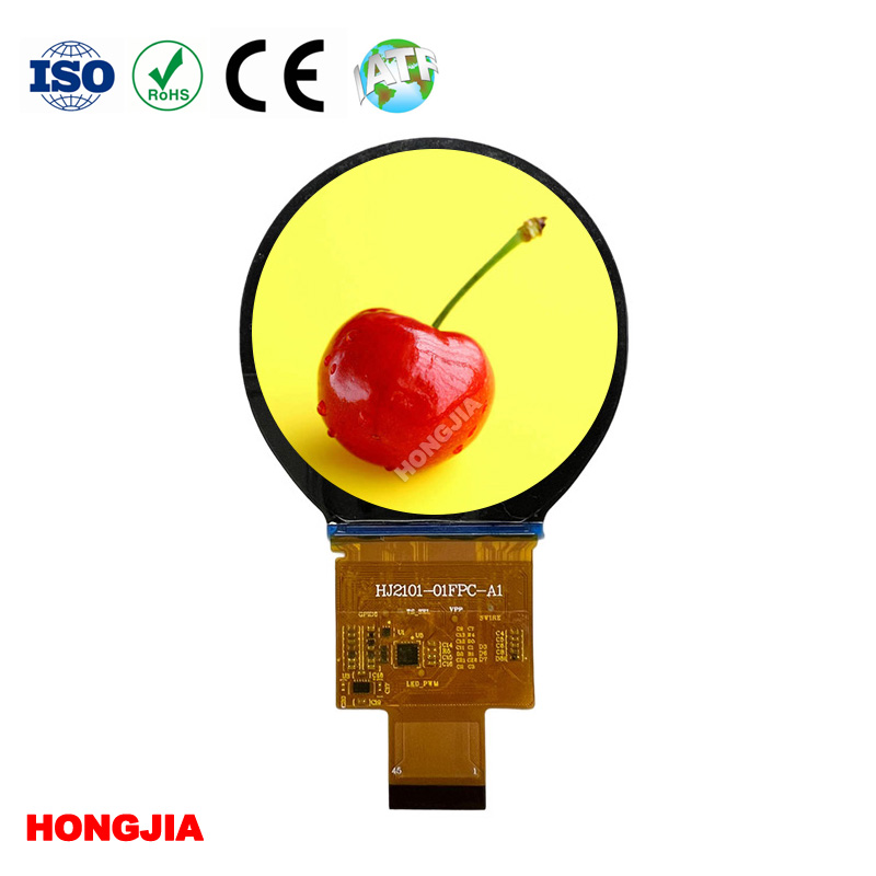
When selecting a compact round display for a wearable device, smart home controller, or industrial HMI, engineers often face a critical firmware decision: which interface protocol delivers the best balance of speed, pin count, and driver compatibility? The 2.1 Inch InCell Round LCD 480*480 QSPI/SPI/MCU from Hongjia addresses this with multiple bus options, but the choice between QSPI (Quad SPI) and traditional MCU (parallel) mode fundamentally impacts your PCB layout, frame rate, and software overhead. This blog breaks down the technical distinctions, performance trade-offs, and real-world application scenarios to help you make the right call for your next project.
Interface Basics: What Each Mode Actually Does
Before comparing, it is essential to understand that both modes serve the same purpose—pushing pixel data from the host microcontroller to the display driver IC—but they do so with entirely different signaling architectures.
| Feature | QSPI Mode | MCU (Parallel) Mode |
|---|---|---|
| Data Lines | 4 bidirectional data pins (IO0–IO3) | 8, 16, or 18 parallel data pins (D0–Dxx) |
| Clock Speed | Up to 60–80 MHz (typical) | Up to 20–30 MHz (due to parallel skew) |
| Max Theoretical Throughput | ~40 MB/s (80 MHz × 4 bits) | ~60–80 MB/s (30 MHz × 16 bits) |
| Pin Count (including control) | 6–7 pins (CS, SCK, IO0-IO3, DC, RST) | 16–22 pins (CS, RS, WR, RD, D0-D15, plus others) |
| DMA Support | Excellent (SPI peripherals common) | Varies (requires dedicated FMC/FSMC) |
| Board Space | Minimal – ideal for dense designs | Significant – challenges for 2-layer boards |
| Software Complexity | Moderate (need to handle command sequences) | Lower (direct memory-mapped writes) |
Performance Deep Dive: Why QSPI Wins for Speed (Sometimes)
In QSPI mode, the 2.1 Inch InCell Round LCD 480*480 QSPI/SPI/MCU leverages dual‑data rate and quad‑lane transfers to achieve impressive throughput. However, the 480×480 resolution at 16‑bit color depth requires 460,800 bytes per full frame. At 60 Hz, you need ~27.6 MB/s of sustained bandwidth—well within QSPI’s theoretical 40 MB/s, but actual performance drops to ~30–35 MB/s after command overhead and chip select delays. For most GUI animations (sliding menus, circular gauges), this is more than sufficient.
MCU parallel mode, on the other hand, uses a write‑only strobe (WR) and read‑only strobe (RD), enabling direct pixel‑by‑pixel updates without command parsing. This reduces latency for small window updates—ideal for real‑time oscilloscope or gaming applications. Yet, the higher pin count forces designers to use larger MCU packages (LQFP-100 vs. QFN-48), which increases BOM cost and assembly complexity.
Hongjia recommends QSPI for battery‑powered IoT devices, where every microamp matters, because fewer toggling pins translate directly to lower dynamic power consumption. MCU mode suits stationary industrial panels where power is less constrained but deterministic response is critical.
Software and Driver Ecosystem
From a firmware perspective, QSPI mode on this 2.1 Inch InCell Round LCD 480*480 QSPI/SPI/MCU requires you to implement a state machine for command–data separation (using the DC pin) and often relies on the vendor‑provided initialization sequence—about 120 registers to configure gamma, porch timing, and voltage settings. Popular libraries like TFT_eSPI and LVGL have built‑in QSPI support for STM32 and ESP32, reducing development time.
MCU mode is simpler: you map the display’s GRAM to the MCU’s external memory controller (e.g., STM32’s FSMC). Writing to a specific address automatically updates the pixel, eliminating software‑based command queues. However, this mode lacks the flexibility of QSPI’s XIP (execute‑in‑place) capability, which allows storing font and image data directly on the display’s auxiliary flash.
Hongjia provides pre‑optimized register tables for both interfaces, ensuring that even first‑time users can bring up the panel within hours rather than days.
Application‑Specific Recommendations
| Application Scenario | Recommended Mode | Rationale |
|---|---|---|
| Smartwatch / Fitness band | QSPI | Low pin count, lower EMI, better battery life |
| Automotive cluster (secondary display) | MCU | Deterministic refresh, no tearing with RGB overlays |
| Home automation touch panel | QSPI | Easy routing on flexible PCBs, supports long traces |
| Handheld gaming device | MCU | Higher burst throughput for sprite rendering |
| Medical monitor (vital signs) | QSPI | Meets stringent EMI/EMC compliance with fewer radiating lines |
The Hidden Factor: InCell Integration
The 2.1 Inch InCell Round LCD 480*480 QSPI/SPI/MCU incorporates the touch controller inside the cell stack, which means the interface you choose also affects touch response latency. In QSPI mode, touch data is usually read via a separate I²C channel, while MCU mode can interleave touch reads during blanking intervals—giving a slight edge to MCU for stylus‑based applications. Hongjia has validated both modes with common touch ICs (FT3267, GT911) to ensure seamless coexistence.
Frequently Asked Questions (FAQ)
Q1: Can I switch between QSPI and MCU mode on the same 2.1 Inch InCell Round LCD 480*480 QSPI/SPI/MCU without hardware modification?
A1: Yes, but only if your PCB breaks out all the necessary parallel data pins AND the QSPI data lines. The driver IC (typically ILI9488 or ST7796 variants used by Hongjia) allows mode selection via an external resistor pull‑up/down on the IM0–IM3 configuration pins. For example, IM0=1, IM1=0, IM2=1, IM3=0 selects QSPI, while IM0=0, IM1=1, IM2=0, IM3=0 selects 16‑bit MCU. However, changing mode on a populated board requires re‑soldering resistors—it is not a software‑only toggle. We strongly recommend deciding your interface at the schematic stage to avoid rework. Hongjia provides a detailed pin‑mapping guide that covers all 12 possible interface configurations.
Q2: Which mode gives better frame rates for full‑screen video playback on the 2.1 Inch InCell Round LCD 480*480 QSPI/SPI/MCU?
A2: For full‑screen video at 30 fps with 16‑bit color, both modes are viable, but MCU parallel (16‑bit) will consistently deliver 30–35 fps under heavy CPU load, while QSPI typically achieves 28–32 fps due to command overhead. However, if your MCU has a dedicated QSPI peripheral with dual‑bank buffering (e.g., NXP i.MX RT series), QSPI can actually outperform MCU by reaching up to 38 fps. The bottleneck is rarely the interface itself—it is the memory bandwidth for decoding JPEG/PNG frames. Hongjia recommends using a GPU‑enabled MCU (like ESP32‑S3 with vector acceleration) for video applications, regardless of mode. Always test with your specific codec pipeline; we offer sample video playback code for both modes upon request.
Q3: Does using MCU mode increase the risk of EMI failure in CE/FCC testing compared to QSPI on this round display?
A3: Absolutely. MCU mode uses 8 to 16 parallel lines switching simultaneously at frequencies above 20 MHz, creating significant harmonic content from 100 MHz to 1 GHz. In contrast, QSPI operates with only 4 data lines and a single clock, substantially reducing radiated emissions. Hongjia has conducted pre‑compliance scans showing that QSPI mode passes Class B limits with a 6 dB margin, while MCU mode requires additional shielding or series termination resistors to meet the same standard. For portable devices subject to strict FCC Part 15 rules, QSPI is the safer choice. We also offer optional EMI‑suppression flexible cables (with ferrite beads) for MCU‑based designs to help you pass certification on the first attempt.
Conclusion & Final Verdict
Choose QSPI if your priority is compact PCB footprint, lower power consumption, and simpler routing—especially for consumer wearables and battery‑operated gadgets. Choose MCU if you need deterministic low‑latency pixel updates, have ample board space, and can tolerate higher pin count and EMI countermeasures.
Both modes are fully supported on the 2.1 Inch InCell Round LCD 480*480 QSPI/SPI/MCU from Hongjia, and we have tested each with over 20 popular MCU platforms (STM32F4, ESP32, RP2040, NXP Kinetis). The decision ultimately rests on your system architecture, not on which mode is "better" in isolation.
Contact Us
We understand that choosing the right interface is just the first step. Hongjia offers free technical consultation, sample initialization codes, and custom FPC (flexible printed circuit) pin‑out modifications to match your specific host MCU. Whether you need a quick‑turn prototype or a production‑ready module with pre‑soldered connectors, our engineering team is ready to assist. Contact us today with your project requirements—we will reply within 4 business hours with a tailored recommendation, datasheet, and competitive pricing. Let us help you bring your round‑display product to market faster and with fewer design spins.